Electrical Connection
Compatible with:
multiScan200
PWR / 8 IOs
System plug part numbers: 2155106, 2148845
The PWR and I/O connection uses a male, 12-pin, A-coded M12 connector.
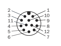
PWR and I/O connector face with numbered pins.
PWR / 8 IOs connector pin assignments and signal functions.
| Pin | Signal | Function |
|---|---|---|
| 1 | IN1/OUT1 |
Configurable digital input 1 or output 1 |
| 2 | GND |
Supply return, 0 V |
| 3 | IN2/OUT2 |
Configurable digital input 2 or output 2 |
| 4 | IN7/OUT7 |
Configurable digital input 7 or output 7 |
| 5 | IN8/OUT8 |
Configurable digital input 8 or output 8 |
| 6 | IN3/OUT3 |
Configurable digital input 3 or output 3 |
| 7 | IN4/OUT4 |
Configurable digital input 4 or output 4 |
| 8 | IN6/OUT6 |
Configurable digital input 6 or output 6 |
| 9 | Vs |
Supply, +9 V DC to +30 V DC |
| 10 | IN5/OUT5 |
Configurable digital input 5 or output 5 |
| 11 | GND |
Supply return, 0 V |
| 12 | Vs |
Supply, +9 V DC to +30 V DC |
Always wire both supply pins 9 and 12 and both ground pins 2 and 11. This is a requirement in the multiScan270 operating instructions, not an optional parallel connection.
Ethernet
The Ethernet connection uses a female, 8-pin, X-coded M12 connector.
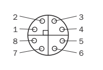
Ethernet connector face with numbered pins.
Ethernet connector pin assignments and signal functions.
| Pin | Signal | Function |
|---|---|---|
| 1 | TRD0_P |
Transmit/receive pair 0 + |
| 2 | TRD0_N |
Transmit/receive pair 0 − |
| 3 | TRD1_P |
Transmit/receive pair 1 + |
| 4 | TRD1_N |
Transmit/receive pair 1 − |
| 5 | TRD3_P |
Transmit/receive pair 3 + |
| 6 | TRD3_N |
Transmit/receive pair 3 − |
| 7 | TRD2_N |
Transmit/receive pair 2 − |
| 8 | TRD2_P |
Transmit/receive pair 2 + |
The X-coded Gigabit Ethernet interface requires all four data pairs. A four-wire D-coded connection is unsuitable.