Electrical Connection
The LRS4000 has separate M12 connectors for power, Ethernet, and digital I/O/encoder signals. The tables below reproduce the assignments from LRS4000 operating instructions 8026337/1VNC, pages 34–35.
PWR
This connection uses a male, 5-pin, A-coded M12 connector.
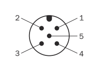
PWR connector face with numbered pins.
PWR connector pin assignments and signal functions.
| Pin | Signal | Function |
|---|---|---|
| 1 | Vs |
Supply, +10 V DC to +30 V DC |
| 2 | — | Reserved; do not connect |
| 3 | GND |
Supply return, 0 V |
| 4 | IN8/OUT8 |
Configurable digital input 8 or output 8 |
| 5 | — | Reserved; do not connect |
Ethernet
This connection uses a female, 4-pin, D-coded M12 connector.
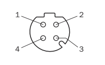
Ethernet connector face with numbered pins.
Ethernet connector pin assignments and signal functions.
| Pin | Signal | Function |
|---|---|---|
| 1 | TX+ |
Transmit + |
| 2 | RX+ |
Receive + |
| 3 | TX- |
Transmit − |
| 4 | RX- |
Receive − |
Connect the D-coded Ethernet interface to an Ethernet port rather than to general-purpose controller terminals.
IOs and Encoder
This connection uses a female, 8-pin, A-coded M12 connector.
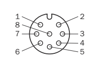
I/O and encoder connector face with numbered pins.
IOs and Encoder connector pin assignments and signal functions.
| Pin | Signal | Function |
|---|---|---|
| 1 | IN1 |
Encoder input 1 |
| 2 | IN2 |
Encoder input 2 |
| 3 | IN3/OUT3 |
Configurable digital input 3 or output 3 |
| 4 | IN4/OUT4 |
Configurable digital input 4 or output 4 |
| 5 | IN5/OUT5 |
Configurable digital input 5 or output 5 |
| 6 | IN6/OUT6 |
Configurable digital input 6 or output 6 |
| 7 | GND INx/OUTx |
Common reference for all digital I/O |
| 8 | IN7/OUT7 |
Configurable digital input 7 or output 7 |