Mounting Frame Setup
This page explains how to assemble the mounting frame used with the SICK Sensor Starter Kits.
The mounting frame provides a stable and adjustable setup for positioning the sensor during demonstrations, training sessions and example projects.
Before you start
Make sure all required parts are available before starting the assembly.
The frame is used as a common setup component for several Starter Kits.
Required Hardware
The following parts are required to assemble the mounting frame:
| Quantity | Component |
|---|---|
| 5 | Aluminum profiles |
| 8 | End caps |
| 8 | Countersunk screws |
| 8 | M5 T-slot nuts |
| 1 | M4 T-slot nut |
| 4 | Angle brackets |
| 1 | Hex key, 3 mm |
Assembly Steps
Follow the steps below to assemble the mounting frame.
Step 1: Prepare the top bar
Use one aluminum profile as the top bar of the mounting frame.
- Take one aluminum profile from the box.
- Insert one M4 T-slot nut into the top groove.
- Insert two M5 T-slot nuts into the bottom groove on the opposite side of the M4 nut.
- Attach two angle brackets using countersunk screws.
- Tighten the screws into the M5 T-slot nuts with the 3 mm hex key.
- Place end caps on both ends of the profile.
- Slide the angle brackets to both ends of the profile and tighten the screws so that the angle brackets and end caps are aligned.
Assembly tip
Make sure the M4 T-slot nut remains accessible on the top side. It will be used later to mount the sensor bracket.
Step 2: Prepare the bottom bars
Use two aluminum profiles as the bottom bars of the frame.
- Insert one M5 T-slot nut into the center groove of each bottom bar.
- Attach one angle bracket to each bottom bar using countersunk screws.
- Tighten the screws with the 3 mm hex key.
- Place end caps on both ends of each bottom bar.
- Position both profiles parallel in front of you.
The profiles should be oriented lengthwise, so the ends point toward you and away from you, not sideways across the table.
Step 3: Attach the vertical bars
Use two aluminum profiles as vertical bars.
- Insert one M5 T-slot nut at the bottom end of each vertical bar.
- Mount each vertical bar at a 90° angle to one bottom bar.
- Use a countersunk screw and the 3 mm hex key to tighten the connection.
- Insert one M5 T-slot nut at the top end of each vertical bar in the groove facing the other bottom bar.
- Place an end cap on top of each vertical bar.
Assembly tip
It may be easier to lay the frame down while mounting the top bar.
Step 4: Mount the top bar
Use the two remaining countersunk screws to mount the top bar between the two vertical bars.
- Position the top bar between the vertical bars.
- Align the angle brackets with the T-slot nuts in the vertical bars.
- Tighten the screws with the 3 mm hex key.
- Adjust the height and angle of the top bar if needed.
- Loosen and tighten the inner screws at the top of the vertical bars to fine-tune the position.
Step 5: Mount the sensor bracket
Mount the InspectorP61x bracket using the supplied M4 screw and washer.
- Position the bracket above the M4 T-slot nut on the top bar.
- Insert the supplied M4 screw with washer.
- Tighten the screw carefully.
- Make sure the bracket is fixed securely.
Expected Result
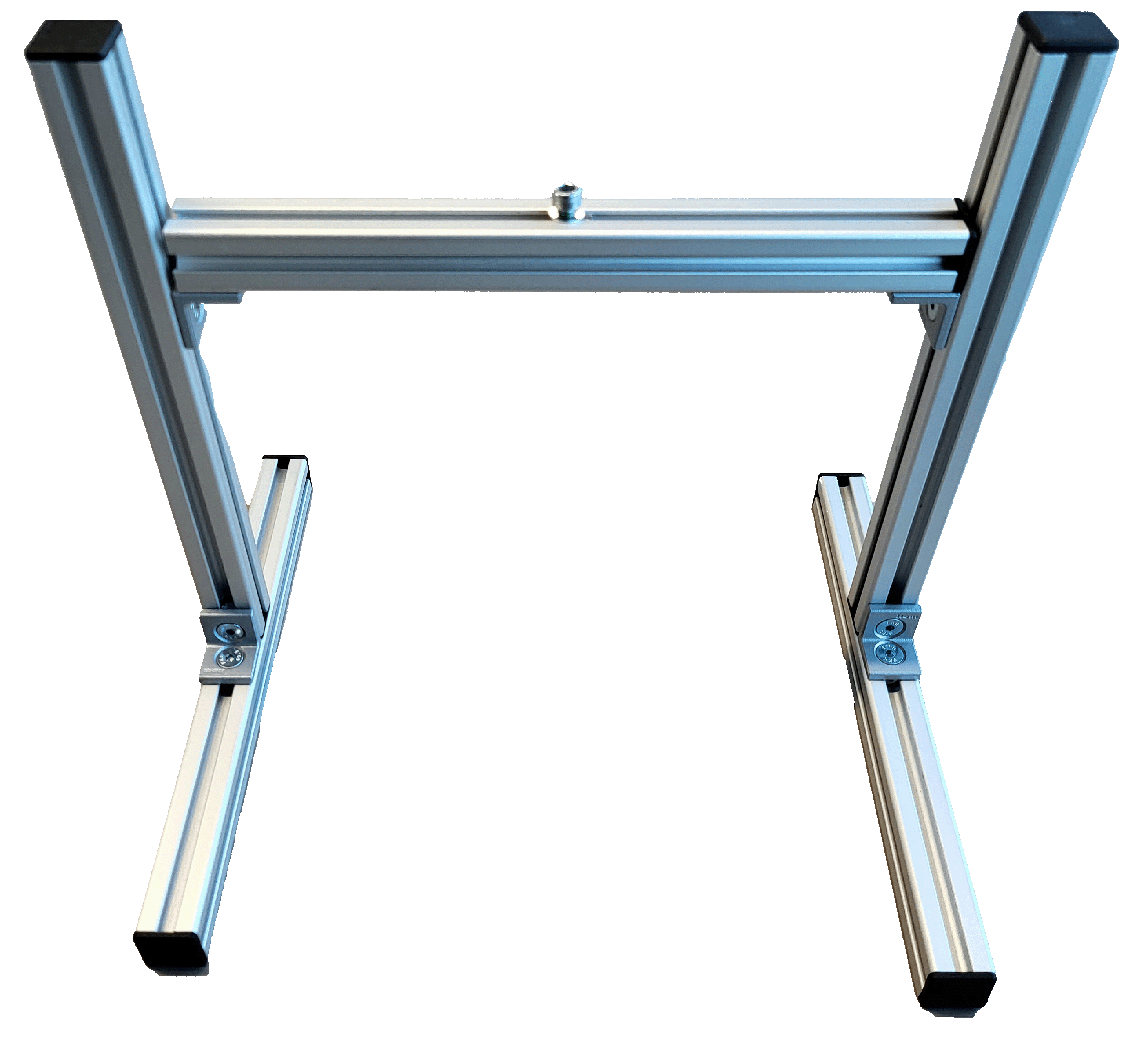
After completing the assembly, the mounting frame should stand stable and provide an adjustable mounting position for the sensor.
The frame is now ready to be used with the Starter Kit setup.
Video Tutorial
The following video shows the mounting frame setup.
Summary
You have assembled the mounting frame and prepared a stable setup for the sensor.
You can now continue with the specific setup guide for your Starter Kit or explore the example projects.